White Paper

Impact of Harmonics in a Distribution Network After Capacitor Bank Placement

Harmonic resonance occurs when the natural frequency in a power system corresponds to the frequency of the harmonic current’s source. Installing capacitor banks in a distribution system without harmonic mitigation can produce a series or parallel resonance condition. While performing integrated voltage VAR control (IVVC) studies, distribution planners need to consider the adverse impact of the capacitor bank in light of potential harmonic resonance.


The electrical power system consists of three interconnected components: generation systems that supply power, transmission systems that transfer the power, and distribution systems that feed it to end users. These systems rely on generators, transformers, transmission lines, cables, switchgear and reactive power compensation equipment to perform their jobs.

Electrical power is produced in renewable and conventional power generating stations owned either by electric utilities or private operators. The electricity, generated at medium voltage, enters into the transmission system via step-up transformers.

Power is transferred over long distances through extra-high-voltage (EHV) and high-voltage (HV) transmission lines before reaching the distribution system, the most complex part of the electrical network.


Read The White Paper

The electrical power system consists of three interconnected components: generation systems that supply power, transmission systems that transfer the power, and distribution systems that feed it to end users. These systems rely on generators, transformers, transmission lines, cables, switchgear and reactive power compensation equipment to perform their jobs.

Electrical power is produced in renewable and conventional power generating stations owned either by electric utilities or private operators. The electricity, generated at medium voltage, enters into the transmission system via step-up transformers.

Power is transferred over long distances through extra-high-voltage (EHV) and high-voltage (HV) transmission lines before reaching the distribution system, the most complex part of the electrical network.

Primary substations connected to the transmission system reduce the power’s voltage so it can be distributed to residential, industrial and commercial consumers through either low-voltage (LV) or medium-voltage (MV) lines and cables. The primary objective of distribution operators is to provide efficient, reliable, high-quality power.

Their jobs are sometimes made more difficult by consumers, who can be major contributors to power quality issues. Nonlinear consumer loads produce harmonics in a power system. Nonsinusoidal current contains harmonic current that interferes with a power system’s impedance, leading to voltage distortion that can affect both the power system and the loads connected to it.

Power quality is further affected by the rapid changes taking place across the electrical power system. The growing contribution of distributed renewable energy resources to the distribution network and total energy supply can not only impact system stability, but also create harmonic distortion. Electric vehicle (EV) charging stations and other technologies may also contribute to total harmonic distortion during battery charging periods.

Another major contributor to distribution system harmonics is the growing volume of equipment that relies on a switched-mode power supply (SMPS). For example, all computer systems use SMPS to convert utility alternating current (AC) voltage to low-voltage direct current (DC) for their internal electronics. These nonlinear power supplies draw current in high-amplitude short pulses that create significant distortion in the electrical current and voltage waveshape. In other words, they create harmonic distortion.

To understand the economic and other impacts of this distortion, operators perform integrated voltage VAR control (IVVC) studies. These studies optimise regulator voltage settings and capacitor bank rating and placement to improve the power factor. The results of an IVVC study can help operators provide a flat voltage profile, helping to reduce losses across a circuit.

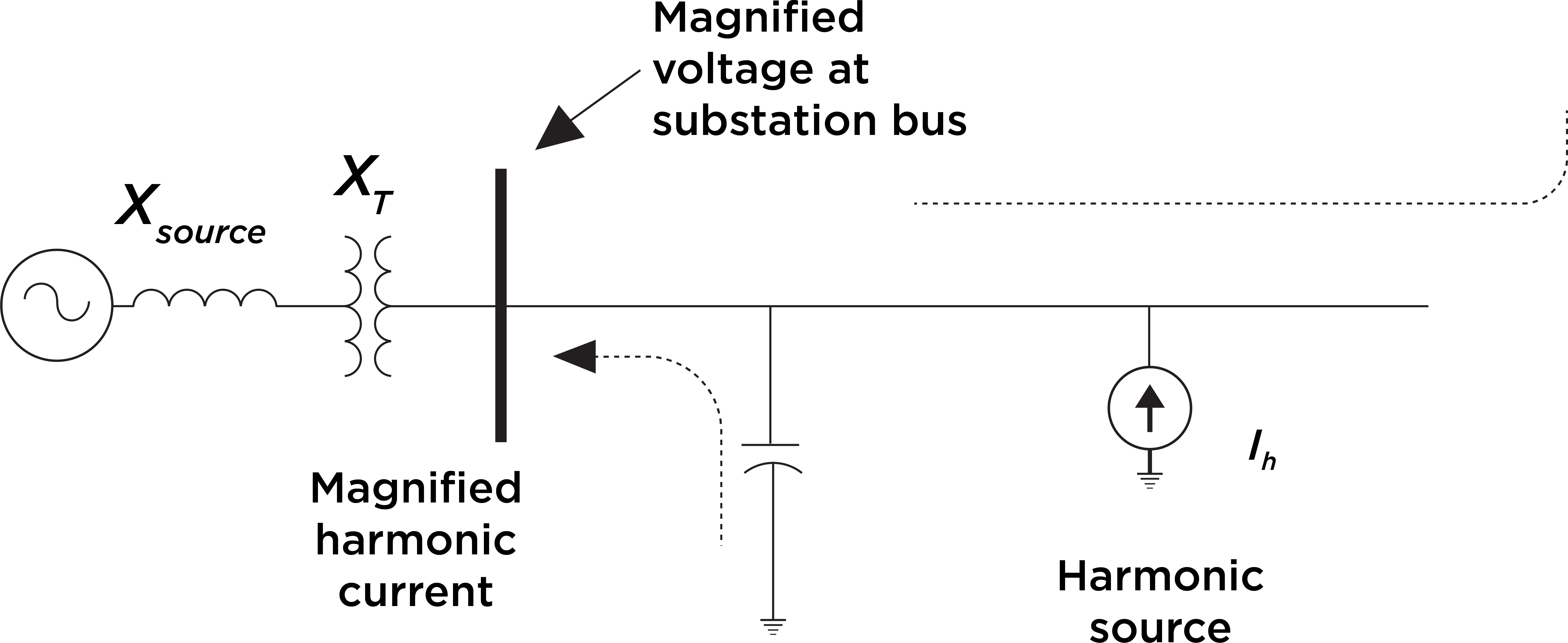
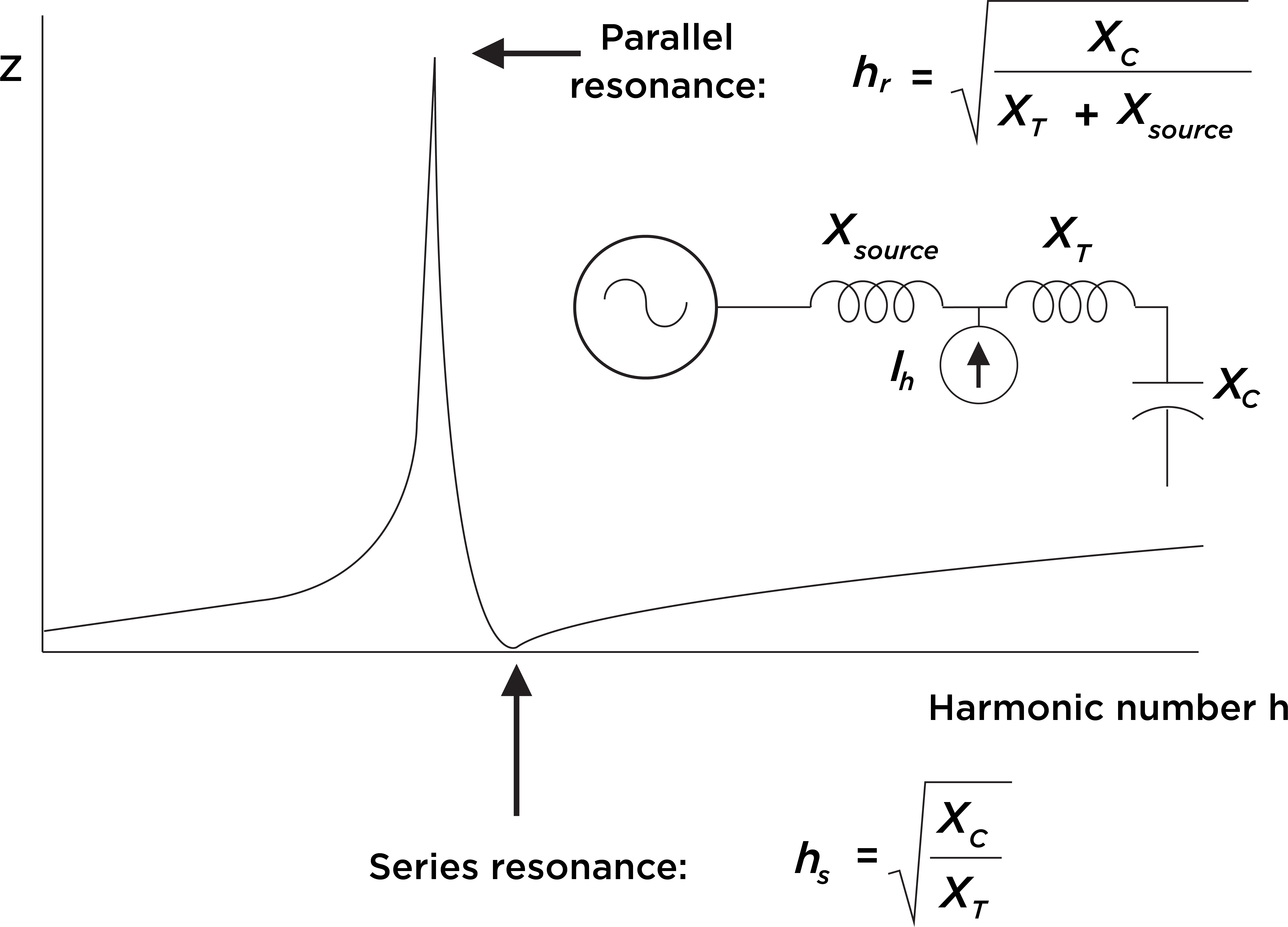
Historically, IVVC studies rarely considered the potentially harmful impact of connecting capacitor banks without harmonic filters. Given the increase in renewable energy sources and EV charging stations connecting to the distribution system, that is changing. These additions contribute to lower-order harmonics in distribution systems, which might cause harmonic resonance conditions that could significantly damage distribution equipment.

Harmonic Resonance

Resonance is a phenomenon that occurs in electrical systems consisting of inductors and capacitors. There are two types of resonance: series and parallel. In parallel resonance circuits, the inductive and capacitive reactance impedance of components is parallel to the source of harmonic current. Harmonic resonance occurs when the order of harmonics at capacitive and inductive reactance is equal. Total effective impedance can be very high in parallel resonance, depending on the system configuration and loading. A shunt capacitor can be installed at an optimal location for voltage support and power factor correction. Capacitor banks can directly affect a distribution system’s resonance frequency and may contribute to harmonic resonance problems.

Parallel resonance (Fp) occurs when the capacitive reactance and the inductive reactance of a distribution system cancel out each other. The frequency at which this phenomenon occurs is called parallel resonant frequency. It can be expressed as follows:

Figure 1: Equation 1.
Leq = Inductance of equivalent, including source and load
C = Capacitance of the capacitor bank.

Figure 2: A typical distribution system with parallel harmonic resonance sources.

At the resonant frequency, the apparent impedance of a parallel combination of the equivalent inductance and capacitance as seen from the harmonic current source becomes very large. It can be expressed as:

Figure 3: Equation 2.

Figure 4: Equation 3.
where Q = XLeq/R = XC/R and R << XLeq.

Keep in mind that the reactance in this equation is computed at the resonant frequency.

Q — often considered the quality factor of a resonant circuit — determines the sharpness of frequency response. Q varies considerably by its location in a power system. It might rate less than 5 on a distribution feeder and more than 30 on the secondary bus of a large step-down transformer. In equation 2, it is clear that during parallel resonance, a small harmonic current can cause a large drop in voltage across the apparent impedance, as illustrated by Vp = QXLeqIh. The voltage near a capacitor bank will be magnified and heavily distorted.

Compare that to current behavior during parallel resonance. If the current flowing in a capacitor bank or into a power system is Iresonance, then:

Figure 5: Equation 4.

Figure 6: Equation 5.

From equation 4, it is clear that currents flowing in the capacitor bank and power system (i.e., through the transformer) will also be magnified Q times. This phenomenon will likely cause capacitors to fail, fuses to blow or transformers to overheat.

Figure 7: In a simplified distribution network for harmonic frequencies, the shunt capacitor bank appears in parallel with the system inductance.

The following graphs illustrate the impedance waveshapes that explain the parallel and series resonance occurrence.

Figure 8: Frequency response of a circuit for parallel and series resonance.

System Configuration

A distribution network analysed for the IVVC study for this paper had the following details:

Parameters

Value

Unit

System voltage of the circuit

12.47

kV

Radial length of the main circuit

24.41

Miles

Summer peak load demand

5,320

kW

kVAR requirement in the circuit (without capacitor bank in operation)

1,335

kVAR

Residential load

74

%

Suggested capacitor bank
- 1 No. – 450 kVAR
- 2 Nos. – 600 kVAR

3

Nos.

After performing IVVC analysis, the pf and voltage of the circuit improved.

Figure 9: Pictorial view of the 12.47-kV distribution network. The orange markers indicate the capacitor placements.

Resonance Analysis

While utility distribution engineers may be able to place capacitor banks with little concern for resonance, harmonic studies always should be performed after capacitor placement in the distribution network and for keeping any future nonlinear loads in mind.

For this paper, an impedance scan was performed to find the order of the harmonic that can create a resonance condition in a distribution circuit. A capacitor bank’s connection point on a circuit is the most critical place where resonance might occur. When parallel resonance occurs at such a location, large amounts of current flow through capacitor banks.

An impedance scan, the preferred method for harmonic resonance analysis, is a relatively straightforward technique. In this case, it was performed at three locations where capacitor banks were proposed. The waveform of the impedance scan shows whether series and/or parallel resonance exists in the system. Impedance seen from a certain bus or node is calculated with a function of frequency.

The harmonic analysis below was performed without considering whether harmonic mitigation equipment was present in upstream systems. The impedance scan results illustrate each phase prior to the placement of any capacitor banks in the circuit.

Figure 10: Impedance scan for individual phases without capacitor banks in operation at proposed nodes for three capacitor bank installation.

Based on the results of the IVVC study, three locations were selected for capacitor installations. An impedance scan was then performed to confirm the impact of capacitor banks operating at nodes in these locations.

Figure 11: Impedance scan for individual phases with capacitor banks in operation at the proposed three nodes for capacitor bank installation.

An analysis of this graph found that the dominant resonance frequency was at approximately the 13th and 14th order of frequency. Resonant conditions occur when capacitors are installed on substation buses or at nodes in the distribution system. In cases where a system has a high X/R ratio, the relative resistance is low and the corresponding parallel resonant impedance is high. This is a common cause of capacitor, transformer or load equipment failure.

Harmonics are the result of nonlinear loads that convert AC line voltage to DC for further utilisation. EV chargers and small- and large-scale renewable generating stations are among the loads that use six-pulse or 12-pulse converters and contribute to nonlinear loads. These converters are known to produce a dominant 13th order harmonic that may lead to resonance conditions in a distribution system that can severely damage equipment and the system itself.

Voltage distortion from capacitor bank resonance may exceed regulatory limits in some cases and require mitigation.

Conclusion

Installing a capacitor bank without harmonic mitigation can have adverse effects on an electrical distribution system.

Utility operators can help protect their systems and equipment by conducting IVVC, conservation voltage reduction (CVR) or other studies that are designed to determine optimal capacitor bank placement. These studies support efforts to optimise voltage and power factors on a distribution network, enabling it to run as efficiently as possible while adhering to load and voltage constraints. Along with the IVVC studies, utilities must perform a harmonic impedance scan.

Until recently, the presence of capacitor banks has not raised issues in distribution systems because of the minimal presence of harmonics required for parallel resonance. But that is changing, given the increased use of nonlinear loads, including EV charging stations and small- and large-scale renewable generating units that use six-pulse and 12-pulse converters. These loads can cause a resonance condition in the distribution system, resulting in severe damage to the system and the equipment used to operate it.

The use of harmonic analysis and voltage VAR control studies is expected to grow. These studies increasingly will be performed concurrently by distribution system planners. Using the results of these harmonic studies, planners must be prepared to implement mitigation techniques to improve distribution system reliability.

Resources

  • N. Eghtedarpour and M.A. Karimi, “Harmonic Resonance in Power Systems — A Documented Case.”
  • Jure Lokar, Janja Dolenc, Bostjan Blazic and Loepold Herman, “Harmonic Resonance Identification and Mitigation in Power System Using Modal Analysis.”
  • Vesna Borozan, Mesut E. Baran and Damir Novosel, “Integrated Volt/VAR Control in Distribution System”
  • William H. Kersting, “Distribution System Modeling and Analysis.”
  • Roger C. Dugan, Mark F. McGranaghan, Surya Santose and H. Wayne Beaty, “Electrical Power System Quality.”

Video Column Complete


Cool Video Headline Goes Here

video description goes here. video description goes here


Authors

Vikram Nawadkar

Principal Engineer

Rajesh Ojha

Associate Senior Engineer

Hari Sharma

Senior Principal Utility Consulting Engineer